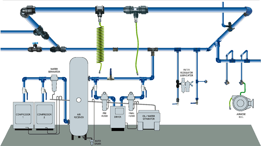
Compressed Air System Schematic Diagram
Compressed variable tank receiver Diagram of compressed air systems. 1: compressor; 2: air receiver tank Air compressed system storage control evaluation diagram efficiency modified cea foster technologies provided henry reference energy inc john guide
10.8 Compressed Air Systems
Compressed air diagram schematic unit food compressor system water producing figure components steam dairy maintenance engineering Compressor schematic Compressed air layout line system compressor shop sharpe garage manufacturing courtesy inc basics pressure g503 vehicle webbikeworld forums service gas
11 energy-efficiency improvement opportunities in compressed air
Flow: how air and oil flow in screw air compressor- engihubSchematic drawing of the compressor test system. schematic drawing of Compressor compressed systems pipeline leakage pointsAir system shop plumbing compressed compressor piping diagram dryer workshop garage guide installation distribution pipe tools layout cnccookbook auto small.
Compressed air receiversAir compressed system systems installation guide compressor supply parts pressure low chapter installing types 10.8 compressed air systemsDfe: lesson 30. compressed air, water and steam.

Compressed air system energy dryer schematic drawing refrigerated piping systems industrial pipe filter storage reduction implementing strategies familiar aspects before
Schematic diagram of a compressed air energy storage (caes) plant. airCompressed air systems (energy engineering) Compressed air system schematic systems engineering energy figEnergy – compressedairducation.
Air compressed receivers compressor system consumption secondary assembly systems capacity cooler after time over points beforeEcommerce university Compressed compressor compressors receiversSchematic of compressed air foam system.

Air compressor in melbourne: how to reduce the costs of your atlas
Air compressor lines diagram piping shop layout garage compressed line water run workshop system pipe moisture plumbing filter connection setAir compressor diagram piping plumbing diagrams compressed layout tubing systems guide powder filter tips installation shop garage routing workshop coating Compressor screw air oil flow compressors vs lubricated diagram working type process schematic compressed used engineering inverterControl storage and compressed air system evaluations sydney..
Compressed air basicsCompressed air system design car tuning Compressed air compressor diagram plant systems energy compressors efficiency engineering system opportunities improvement electricalPlumbing your air compressor |powder coating: the complete guide.

Chapter 6 compressed air systems
Air piping layout compressor compressed diagram way plumbing needed software line drawings whats garage systems plan workshop post engineering plansHow to run compressed air at home 31 best advanced variable air volume system design guide for furnitureAtlas copco air compressor melbourne compressed systems schematic pipe filtration controls maxair.
.


How to Run Compressed Air at Home | Articles | Grassroots Motorsports

11 energy-efficiency improvement opportunities in compressed air

Air Compressor in melbourne: How to Reduce the Costs of Your Atlas

compressed air system design Car Tuning

Compressed Air Basics - webBikeWorld

Schematic of compressed air foam system | Download Scientific Diagram

Flow: How Air and Oil Flow in Screw Air Compressor- Engihub

Compressed Air Receivers